How it works
A sensor network in the Arctic fails for boring reasons. Batteries run flat, a relay dies unnoticed, and nobody finds out until the next field season. The design answer is a radio that knows exactly when to wake up.
01 / The network
Sensor nodes talk to a nearby relay. Relays forward toward a single gateway, which is the only device needing a connection to the outside world. One uplink serves the whole site.
Three roles, one set of hardware
02 / Why it lasts
Most low-power radios waste their battery waiting for something to arrive. Every node here is given a precise slot, so it wakes, does its business and goes back to deep sleep. Nothing idles with a receiver open.
One reporting cycle, radio on for roughly 100 ms
03 / When something breaks
Every node keeps a list of the other relays it has heard from. When its parent stops beaconing, it promotes one of them and re-registers. There is no manual topology file and no site visit.
A failed hop is replaced from the neighbour list
04 / Power-aware routing
A relay advertises what it costs to send through it, and that cost rises as its battery falls. When a relay runs low, the nodes around it send their readings another way. Once it has recharged, it is the cheapest route again and the traffic comes back.
A relay runs low, traffic moves away, then returns once it has charged
05 / Pricing a hop
Routing cost is not hop count. Each link is priced from how far the signal has to travel, how much battery the receiving relay has left, and how many hops remain to the gateway. A node adds up the price of each route it could take and sends along the cheapest.
The nearer relay is low on battery, so the route through the other is cheaper
06 / Joining
Discovery
It listens for relay beacons, picks a parent, and keeps every other relay it heard as a fallback.
Join and slot assignment
It registers with that parent and is given a slot. From here the radio schedule is fully determined, so there is no reason to open a receiver at any other time.
Synchronised operation
The gateway is the time anchor, and time propagates down the tree. Slots stay aligned as the hardware warms and cools.
07 / The hardware
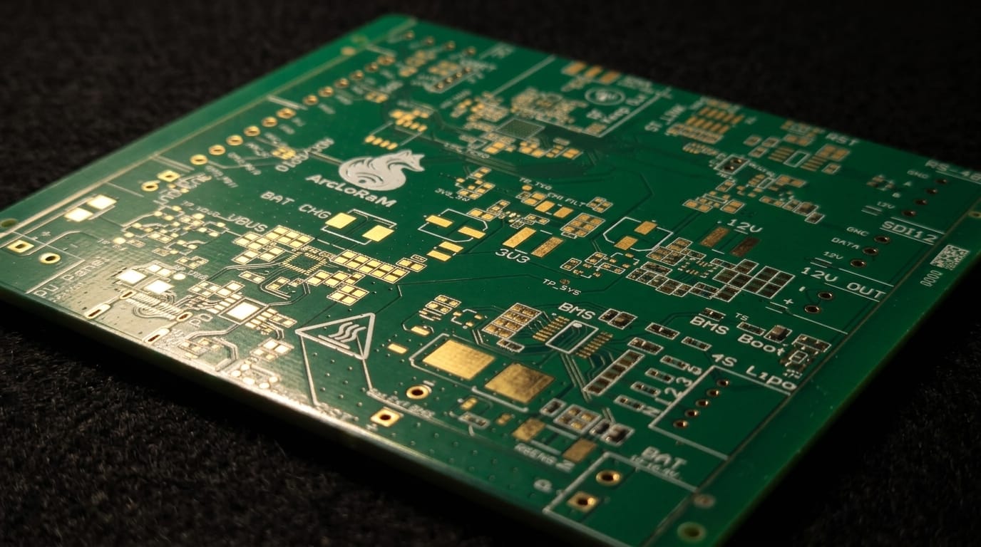
A C1, a C2 and a C3 are the same hardware in different configurations, so a deployment is one part number to build, stock and repair. Instruments connect over the interfaces operators already have, rather than requiring a new capital base of probes.
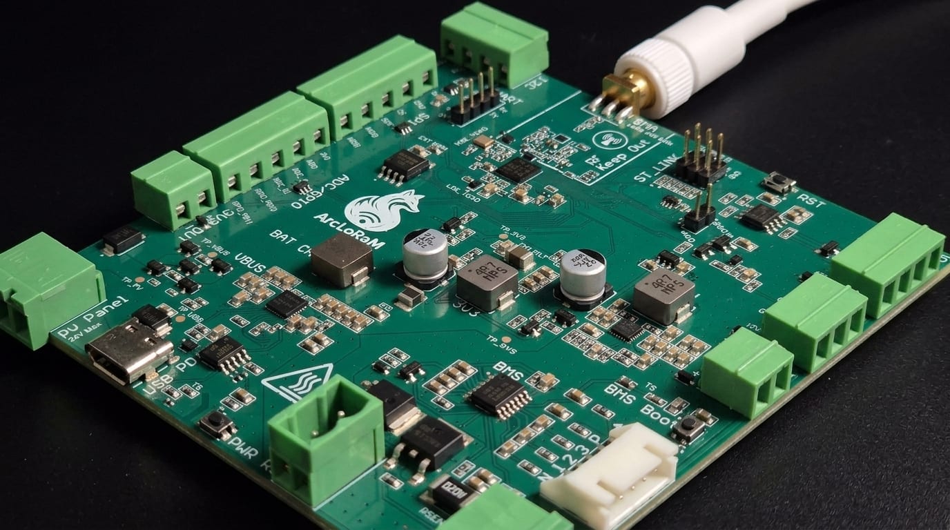
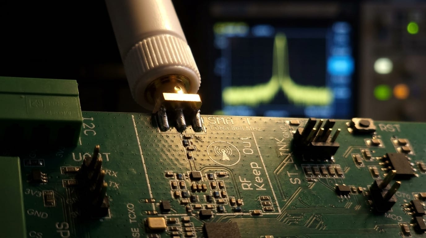
Validated in a climate chamber to -40°C.
One board set, configured as sensor, relay or gateway.
868 MHz, license-free across the EU and Greenland.
Three roles, compared
Sensor
Carries the instrument.
Relay
Forwards across the mesh.
Gateway
The sink for all data.
Inside one node
- In each reporting cycle
- radio on for roughly 100 milliseconds
- Enforced in firmware, not left to the operator
- a duty cycle of 1 percent
- ETSI M-band, license-free in the EU and Greenland
- 868 megahertz
- Measured across temperature in the chamber
- 0.03 parts per million
Shared by all three
08 / Honestly
The hardware has been validated in a climate chamber to -40°C, where over 98% of about 19,600 packets were acknowledged and the crystal clock held to 0.03 ppm. That is a measurement.
Field life, coverage and range are modelled from component behaviour and have not been observed over a season in the field. We publish them as design targets, marked as such, and will replace each one with a measurement. The first field deployment is planned for summer 2027.
Every figure, in one place
Measured values and V2 design targets, side by side and labelled.
See them on Why Nuna